by Darrell
28 September 2016
Math, Model, Measure
PartQuest Explore is the perfect online circuit simulation environment for engineering studies. The cloud-based simulator allows students to explore and verify electronic designs, prior to building a prototype, to both learn more effectively and to be more efficient with time and resources in the lab. It's the perfect modeling tool to bridge the gap between the theoretical math world of transfer functions and physics, and the empirical world of lab measurements.
Common Emitter Amplifier Circuit
This example was provided by an MSEE student. The student used PartQuest Explore in a homework/lab project for an Analog Communications Course. In this lab, the students were asked to design a common emitter amplifier circuit, using PartQuest Explore, and then verify the functionality by building a physical prototype and measuring the performance.
While exploring various options for the amplifier design, the student used design equations, derived analytically, to determine the relationship between parameter values and the amplifier input-to-output voltage gain. Then, PartQuest Explore was used to fine-tune the values to achieve and/or verify the desired gain. The student then built a prototype by soldering the selected parts onto a single-sided, copper-plated board and measuring the result with test equipment.
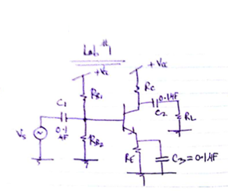
Common Emitter Configuration
Figure 1. The Common Emitter Amplifier Circuit
Theoretical Considerations
Design Specifications: Design a common emitter amplifier to given a give a gain of 15 (23.5 dB) when the source resistance is equal to zero and load resistance is 50 ohms. There is a single power supply value that is chosen between 5V and 10V. Design and simulate the circuit to get a gain. The capacitor values should be 0.1 microfarads.
A few simplifying assumptions and a bit of circuit analysis, followed by simple algebra yields an equation for the amplifier voltage gain as a function of the circuit parameters and a couple of constants:
where is the so-called p-n junction thermal voltage (~25 mV) and
is the approximate voltage drop for a forward biased p-n junction (0.7 V).
So, for the following values:
This is equivalent to 24.4 dB gain with 180º phase shift.
This result matches favorably with the simulation shown above in Figure 1.
Lab Prototype

Figure 2. Common Emitter Prototype Board
Measurements were made on the circuit board in Figure 2. The input voltage, Vin, was a 10 mV (peak-to-peak) sine wave at both 5 MHz and 10 MHz, supplied by a function generator. The output voltage, Vout, was measured with an oscilloscope. At 5 MHz, the output was 120 mV, peak-to-peak, and at 10 MHz it was 122 mV. This corresponds to a gain of 12 (21.6 dB) and 12.2 (21.7 dB), respectively.
From the simulation, in Figure 1, the 5 MHz value compares relatively well at approximately 19.6 dB. But the 10 MHz simulation falls off to about 15 dB, rather than 21.7 dB in the measurement.
Conclusions
Overall, the design equation approximation for the amplifier gain was accurate enough to be useful in selecting component values. The PartQuest Explore circuit simulation provided a higher degree of accuracy to determine the theoretical behavior of the amplifier, over the frequency range of interest. The measured results agreed within reasonable experimental error.
Resources for further reading
Wikipedia Common Emitter Amplifiers
Electronics Tutorials - Common Emitter Amplifiers
All About Circuits - Common Emitter Amplifiers
Acknowledgments

Thanks to Ramya Mahadevan for contributing the circuits and photos for this blog. Ramya was an MSEE student at the University of Illinois, Chicago when she did this work.
- 139 views