by Mike Donnelly
2 December 2016
In my previous blog, “Mechatronics Engineers … Start Your Motors”, I mentioned that we were working on two additional motor types, a Switched Reluctance Machine (SRM) and a Stepper Motor. I’m now happy to report that they have been added to our component library, under the category Magnetic and Electro-mechanical. There you’ll also find our complete set of rotating and linear machine models:
- DC
- Induction
- PMSM
- BLDC
- SRM
- Stepper
- Electromagnet (solenoid)
- Linear DC Motor (linear actuator)
With this set of models, our users can explore a wide range motion control, actuation and power generation systems. Let’s take a look at a couple of new examples.
This design shows a stepper motor's ability to control a load angle, not by using a rotation angle sensor for feedback, but rather by simply counting steps. In this case, 8 steps are taken in the forward direction, followed by 2 steps in the reverse direction, repeating this cycle every 1 second.
The load angle (brown waveform) is seen to increase and decrease as commanded by the direction control signal (light blue waveform) and a 100ms periodic "d_step" input (not shown, but you can move any of the waveform probes to see it, or place a new probe from the schematic toolbar). But on the 4th step of the second cycle, the wind-up spring's torque exceeds the capability of the stepper motor, causing it to "snap back" suddenly to a negative angle, below the initial starting point! This “dramatic” result illustrates the need to including all the relevant “system context” when designing a motor and its control electronics.
Note that the phase currents of the motor (red and dark blue waveforms) reflect the sequencing of the drive switches in the forward and reverse direction. This is an "Interactive" design, so you can change the battery voltage or the spring stiffness and run a new simulation to see the effect of your change.
Switched Reluctance Motor (SRM) driving a Fan Load
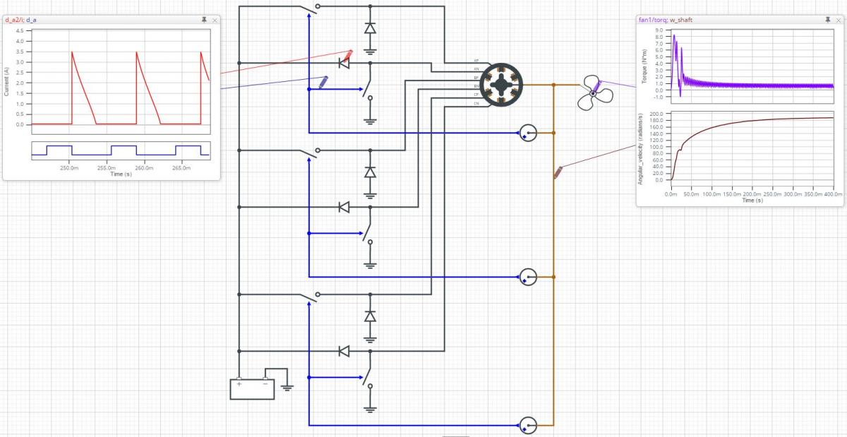
This second example shows an open-loop fan drive system with a 48V DC supply. It runs at just under 1800 RPM (187 rad/sec, brown waveform), generating 100 Watts of mechanical power but with significant torque ripple (purple waveform).
The drive uses a simple switching scheme to energize and de-energize the three phase windings of the SRM. The switches are controlled by 3 index sensors that align the windings' activation and de-activation with the desired rotor angle. Note that when de-energizing a winding and the switches are opened (blue waveform), the current (red waveform) continues to flow from ground to the battery connection via the diodes, thus returning energy stored in the winding inductance back to the supply. Once that current reaches 0.0A, the now reverse biased diodes prevent current reversal and re-energizing of the winding.
Summary
In addition to the motor or machine models mentioned above, PartQuest Explore also provides a large set of control and transformation blocks (e.g. Clarke/Park), analog and digital electronics, as well as mechanical/hydraulic and other building blocks to represent the load’s static and dynamic characteristics. There is also unlimited model creation capability, so you can develop and execute your own sample-data control algorithms, custom sensors and new/advanced machine models. PartQuest Explore is powerful modeling and simulation platform for designing mechatronic systems.
- 110 views