by Mike Donnelly
21 November 2019

In my previous article I demonstrated an important self-protection feature of the NCV84160 from ON Semiconductor; its ability to enter thermal limit cycling if the internal device temperature gets too high. My friend and fellow model-developer, Alain Stas of Vishay, recently suggested that NTC thermistors could be used to provide similar protection at the circuit board or system level. One application where this could be implemented in a very natural way is for LED lighting systems.
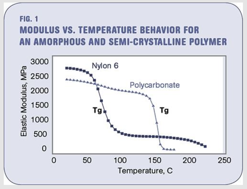
Figure 1: Tg* for Nylon 6 occurs at 70 - 75C (RE: “The Effects of Temperature”)
LEDs are typically dimmed using PWM control. In the application circuit below, the LED driver electronics and three LEDs are assumed to be in an enclosure with a polymer (Nylon 6) lens. It is desirable to keep the enclosure temperature below Tg, the “glass-transition temperature”, to avoid potential deformation of the lens when the outside temperature rises. Reducing the internal heat dissipation by dimming the LEDs is a way to extend the ambient operating temperature range of the system.
Vishay has recently provided high-fidelity models of their thermistors in the Partner Library of PartQuest Explore. Both self-heating and external thermal coupling behavior is modeled. That is, each thermistor model includes a “thermal terminal” (red connection) so they can be attached to an external thermal network representing the system’s dynamic thermal characteristics. One of those models, an NTCS0603 is used in this design (bottom of the schematic).
The NTCS0603 senses the enclosure temperature**, which depends on the dissipation heat flow from each of the power electronics devices, as well as the step-wise increasing outside air temperature. The electrical feedback (i.e. the NTC resistance change) of the thermistor, which is used in a bridge configuration, controls the PWM dimming of the LEDs. It thereby limits the internal temperature rise when operating at high outside temperature conditions. For this nominal configuration, PWM begins when the outside temperature is 50C, and the LEDs are completely off when it reaches 70C, eliminating all self-heating.
Since this is a “Live” design, you can change key parameter values (shown in blue) and then run new simulations to see the results. These include:
- r_mirror, the resistance of the current mirror that controls the capacitor charging rate of the 555 timer, and thereby sets the PWM frequency
- r_offset, the resistance that controls the temperature level at which the dimming operation begins
- r_iLED_set, the resistance that controls the ON-state operating current of the LEDs
- Try a different part number from the same Vishay thermistor family
Try it yourself!
As mentioned in the linked reference above and in the footnote, the value of Tg for Nylon 6 and other polycarbonates can vary widely, so the requirement for the shut-down temperature limit may also vary. This design can accommodate that change by adjusting the resistance “r_offset”. To try this, just double-click on r_offset and change its value from 1.5k Ohm to 3.5k Ohm and run a new simulation. Note that the PWM dimming now begins when the outside temperature is between 30 and 40C, and the LEDs are completely off when the temperature reaches 50C.
You can also press the yellow "Edit in PartQuest Explore" button and open a copy of this design of your own. You can then completely change the design, including selecting and placing other parts from the model library.
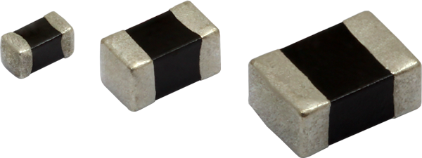
Figure 2: Vishay SMD NTC Thermistors with Enhanced Stability
--------------------------
*Tg for Nylon 6 can vary between 50C and 100C.
**To reduce the time needed to simulate the transition and settling at 6 different temperature levels, all thermal time constants were reduced by approximately 1000x. The actual thermal response time constant of the NTCS0603 is approximately 3 seconds (depends on mounting), not 3 msec! The enclosure thermal capacitance was similarly reduced. This time scaling does not affect the static relationship between the outside temperature and PWM dimming.
- 635 views