by Mike Donnelly
21 April 2018
Electric Power Steering (EPS) systems provide a challenging control design problem for system integrators. Because the system directly interacts with the driver’s hands, reducing vibration is a must. But controlling the system’s fundamental mechanical resonance requires loop compensation, such as lead, which can make the system sensitive to higher frequency disturbances (1). This can include cogging and torque ripple from the motor, or commutation noise from the drive electronics. For this reason, it is essential to have a tool flow that supports a coordinated design effort across these technologies.
Figure 1. EPS System with Ideal PMSM and Drive
Note: This is a "tunable" design. Many of the system parameters can be changed by the user. Then a new simulation can be run and the updated results can be observed in the waveform viewers. Changable parameters are shown in blue, you many need to zoom in to see them clearly.
Figure 1 shows an EPS System design that includes an ideal Permanent Magnet Synchronous Machine (PMSM) model, as well as a continuous D-Q controller and drive circuit. The mechanical load model includes static and kinetic friction, a steering force that varies with rack displacement, as well as various mass, inertia, damping and spring/stiffness elements of the steering system. The steering torque, applied by the vehicle's driver, is assisted by torque from the motor scaled by the gear ratio. For the control, a non-linear gain profile is specified in the "torque_assist_table" function, and a lead-lag compensator is used to improve system stability.
The simulation results indicate a relatively smooth response to a sinusoidal steering wheel angle change of 90 degrees peak-to-peak, over a 1 second time interval. Note in particular, in the upper right graph, that the assist torque (red waveform) is approximately 3x the driver’s applied steering torque (blue waveform), with little vibration except at transitions through the zero commanded torque dead-band, as specified by the torque-assist profile. Note there is also some initial disturbance due to stick/slip load friction. (You may need to expand the size of the waveform viewer to see the detailed features of these signals)
Once the design is considered acceptable at the conceptual phase, more detailed component design and selection can begin. Very fast and effective motor design can proceed using Simcenter E-Machine Design (formerly Simcenter Motorsolve):
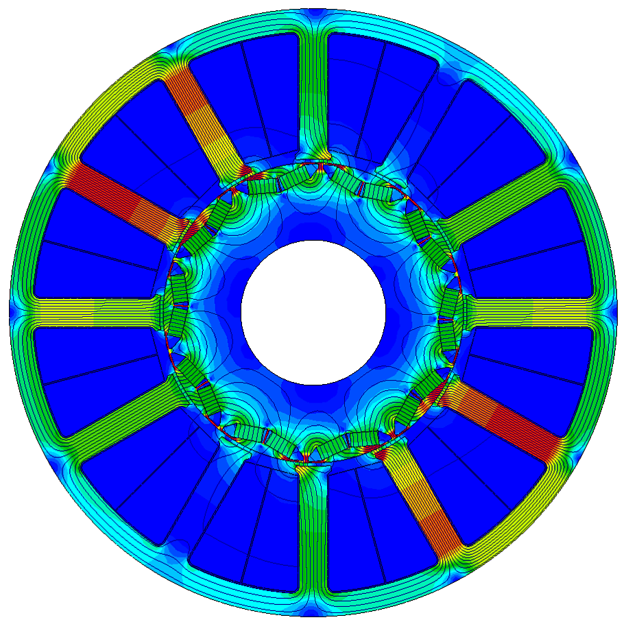
Figure 2. E-Machine Design B-field Analysis of the EPS PMSM Motor
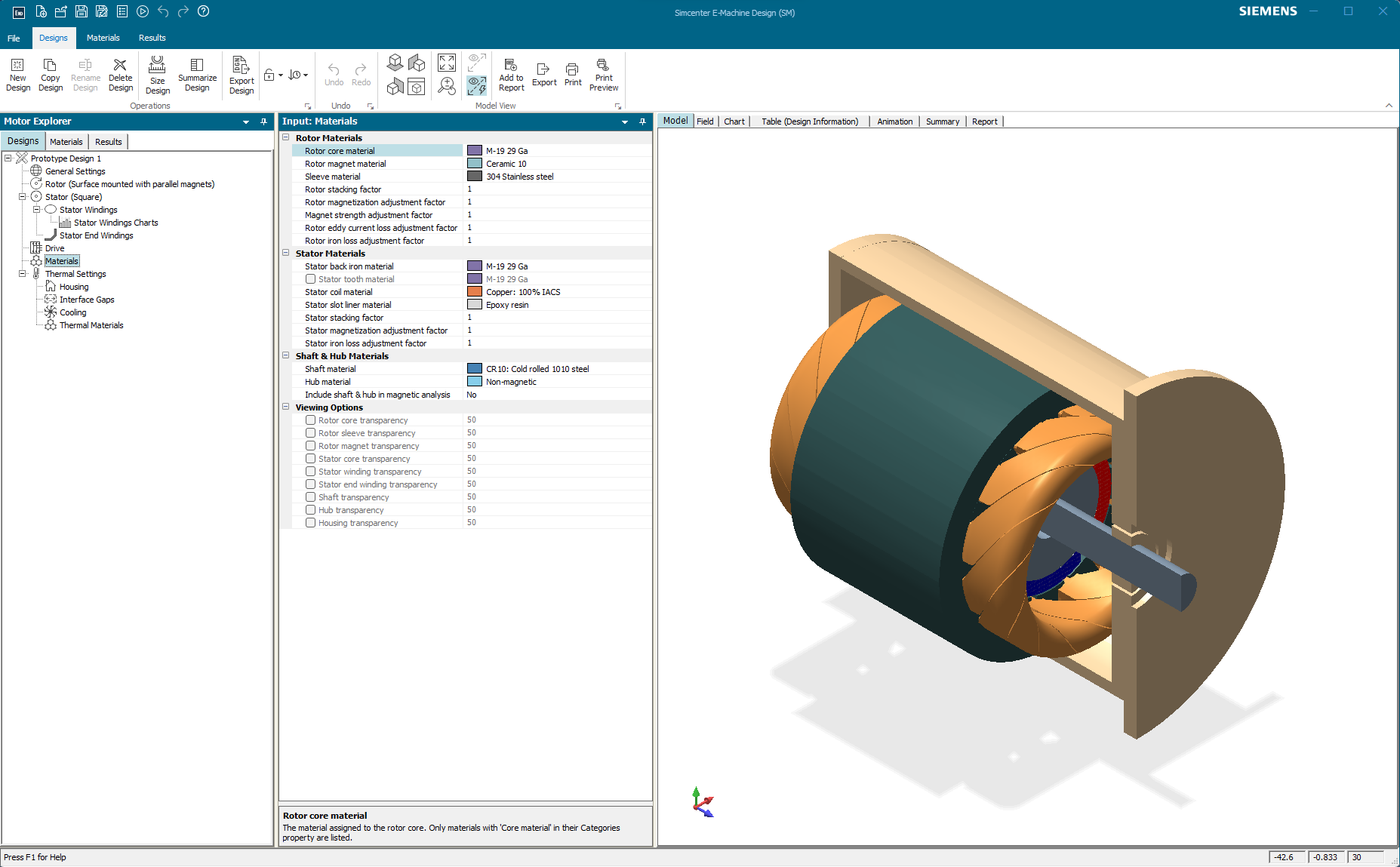 Figure 3. E-Machine Design 3-D rendering of the EPS PMSM Motor
A critically important capability of E-Machine Design for system-level design is that it can export a “1-D” machine model in the IEEE Standard VHDL-AMS format. Those models can therefore be directly imported into PartQuest Explore, for “virtual integration” with the rest of the EPS system, as shown below:
Figure 4. EPS System with high fidelity E-Machine Design generated PMSM model
Note: This design is also “tunable”, you can change parameters in blue and re-run the simulation.
The version of the EPS System design shown in Figure 4 includes the E-Machine Design generated IPM - PMSM motor model. Its behavior includes cogging, saturation, torque ripple and other realistic machine characteristics. The simulation results, especially the red torque assist waveforms, indicates that these parasitic machine characteristics can cause a vibration that may be noticeable to the vehicle driver. Expand the viewer to see the small ripple in the blue torque waveform that is directly applied to the steering wheel.
Figure 5. Full EPS System with high fidelity E-Machine Design PMSM model and DQ/SVM drive electronics
Note: This is a “Live - View” design. You can move waveform probes around and see other signals, but you can't change parameter values.
Finally, in Figure 5, an even higher fidelity EPS System model is shown. This version includes not only the E-Machine Design generated PMSM model, but also a more “physical” representation of the drive electronics. This includes a sampled-data D-Q control algorithm, with space-vector modulation (SVM) to generate digital PWM signals to control the switches of the 3-Phase inverter.
This article illustrates a tool flow, starting with high level (conceptual) modeling and analysis of the integrated system, followed by the physical design and analysis of a suitable machine. Then finally virtual verification of that machine “in-the-loop”, using higher fidelity models of the hardware and control algorithms as their implementation details become available.
---------------------------
(1) D. Lee, K-S Kim and s. Kim, “Controller Design of an Electric Power Steering System”, IEEE Transactions on Control Systems Technology, Vol. 26, No. 2, March 2018
Note: Simcenter E-Machine Design is the next generation of Simcenter Motorsolve
- 565 views