by DanielPecora
28 November 2016
While working from home, a PCB designer may not have access to expensive power supplies to test fairly simple boards. By using low-noise linear voltage regulators, you can create a customizable power supply using 9 different voltages, ranging from 2.5 to 15 V. The power supply is equipped with an AC to DC converter, making it transportable for the do-it-all engineer. With easy access to this adjustable power supply, you do not need gigantic power supplies to complete your testing.
The simulation model of the Adjustable Power Supply is shown below:
Figure 1: PartQuest Explore Schematic of Solderless Breadboard Power Supply
Note: This schematic is editable, so you can zoom in and out, move waveform probes around and look at signals on any of the nets (i.e "wires"). You can see the parameter values by double-clicking on the components. Also, you can save your own copy by clicking on "Edit in PartQuest Explore" . Within PartQuest Explore, you can change specific parameters and re-simulate the circuit.
The J1 on the left side of the schematic shows the power jack for the AC to DC conversion. The Schottky diode connected the the first pin of the power jack prevents reversed polarity voltage from reaching other components. The SW1 is a switch to turn on and off the DC input. R2 provides a quick discharge for C1. The capacitors C1 through C4 will reduce noise and provide filtering. The LED in series with R1 will indicate that the oscillation suppression for U1 is properly working.
Component Selection
The parameters for U1 and R1 are determined by what output voltage the user would like to have. For example, if you would like to generate 12V output, you would need a specific regulator for U1 and R1 should be 2k. The following table shows what regulators and resistor values you should use for the 9 different output voltages:
| U1 | Digi-Key PN | VOUT | IOUT (Max.) | VIN (Min.) | VIN(Max.) | R1 (Ohms) | Digi-Key PN |
| LM2937-2.5 | 296-39757-5-ND | 2.5 | 500 mA | 4.75 | 26 | 82 | 82QBK-ND |
| LM2937-3.3 | LM2937ET-3.3/NOPB-ND | 3.3 | 500 mA | 4.75 | 26 | 220 | 220QBK-ND |
| LM7805CT | LM7805CT-ND | 5 | 1 A | 7 | 20 | 560 | 560QBK-ND |
| LM7806CT | LM7806CT-ND | 6 | 1 A | 8 | 21 | 750 | 750QBK-ND |
| LM7809CT | LM7808CT | 8 | 1 A | 10.5 | 23 | 1.2k | 1.2KQBK-ND |
| LM7809CT | LM7809CT-ND | 9 | 1 A | 11.5 | 24 | 1.3k | 1.3KQBK-ND |
| LM7810CT | LM7810CT-ND | 10 | 1 A | 12.5 | 25 | 1.6k | 1.6KQBK-ND |
| LM7812CT | LM7812CTFS-ND | 12 | 1 A | 14.5 | 27 | 2k | 2.0KQBK-ND |
| LM7815 | LM7815CTFS-ND | 15 | 1 A | 17.5 | 30 | 2.7k | 2.7KQBK-ND |
From Table 1, the maximum current given for each voltage regulator IC is a theoretical maximum under ideal conditions. Luckily, all of the regulator ICs have a thermal shutdown function that will turn off the IC if they overheat. Once they cool down to an appropriate temperature, they will resume their normal functionality. Also, the current coming from the power jack must generate the current listed in the Iout column.
Subsequently, the minimum and maximum voltage inputs for the voltage regulators are included. This will ensure that the voltage being fed from the power jack is properly managed. Also, if the input voltage increases, the temperature dissipated by the voltage regulator IC will increase as well. Thus, it is sensible to use an AC to DC converter that is as close to the minimum voltage as possible.
Here is a video tutorial on how to create the voltage regulator within PartQuest Explore:
PADS Integration
If you currently use PADS in your PCB design flow, you can easily integrate PartQuest Explore. This is done by using the PartQuest Explore import tool. Once the import tool has been installed, you simply select "Tools" > "Import from PartQuest Explore". You can select the schematic you would like to open and DxDesigner will automatically redraw the circuit.
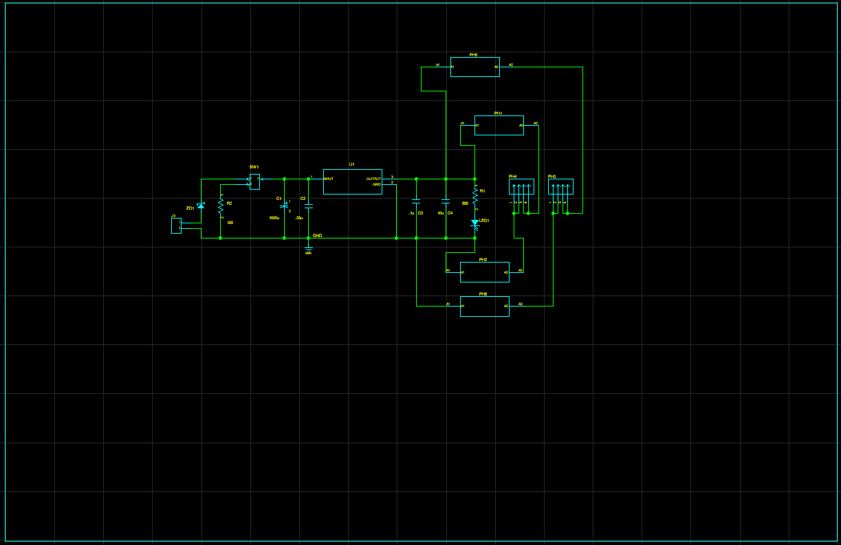
Figure 2: DxDesigner Schematic of Breadboard Power Supply

Figure 3: Layout of Breadboard Power Supply
Time to get the PCB!
Once you have simulated the board and properly laid out the components and traces, it is time to send it to a manufacturing facility. You can find multiple facilities that will make inexpensive boards for this simple board. Once you send over the specific PCB files, it will typically take about 3 to 5 weeks for the boards to arrive.
Finally, you may start constructing your board! This is be a fairly easy process since there are few components for this board and the size of the pads are relatively large for soldering. When completed, you will be able to test other potential designs that you have been working on.
Using PartQuest Explore’s simulation models, you should be able to detect any issues before you begin laying out the board. The moveable waveform probes make it easy to see the parameters of each net (or wire) before you begin laying out the board. Since it is a cloud-based system, there is no download required and all you have to do is login to continue working on your design.
How to Get Started with PartQuest Explore
If you are new to PartQuest Explore, please check out “How to Get Help with PartQuest Explore”:
- Getting Started Video
- Expert Guided Tour Webinars
- Discussion Forums
- Intercom Chat (hint: blue icon in lower right)
- Application Help (hint: "?" in application tool bar)
The author would like to thank Charles R Hampton from All About Circuits for creating a nice writeup on this technology.
You can see what he has done here: http://www.allaboutcircuits.com/projects/build-9-linear-voltage-regulat…
- 134 views